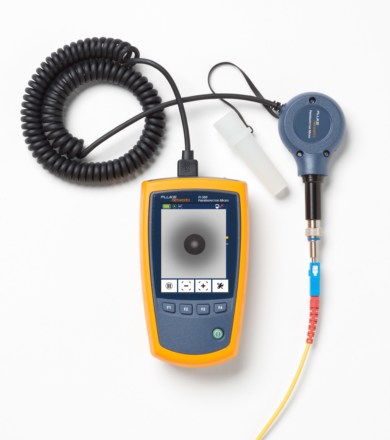
Using FI-500 Micro for Fiber Endface Inspection
Endface Inspection on Fiber Patch Cord or OTDR Fiber Launch Cord
To view an endface on a fiber patch cord or an OTDR fiber launch cord, insert the ferrule of the fiber connector to be inspected into the probe tip on the FI-500 probe and press the AF (Auto Focus) button.
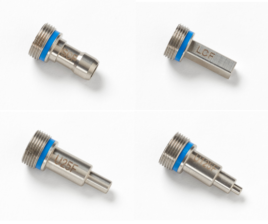
- Probe tips with blue bands are suited for testing UPC endface finish fiber connections.
- Probe tips with green bands are suited for testing APC endface finish fiber connections.
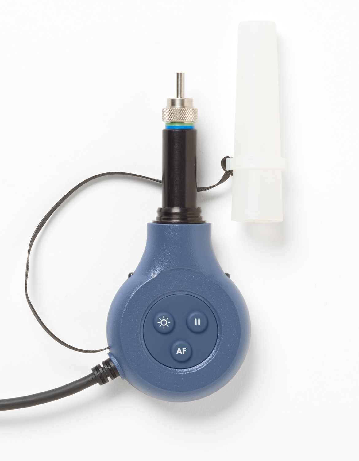
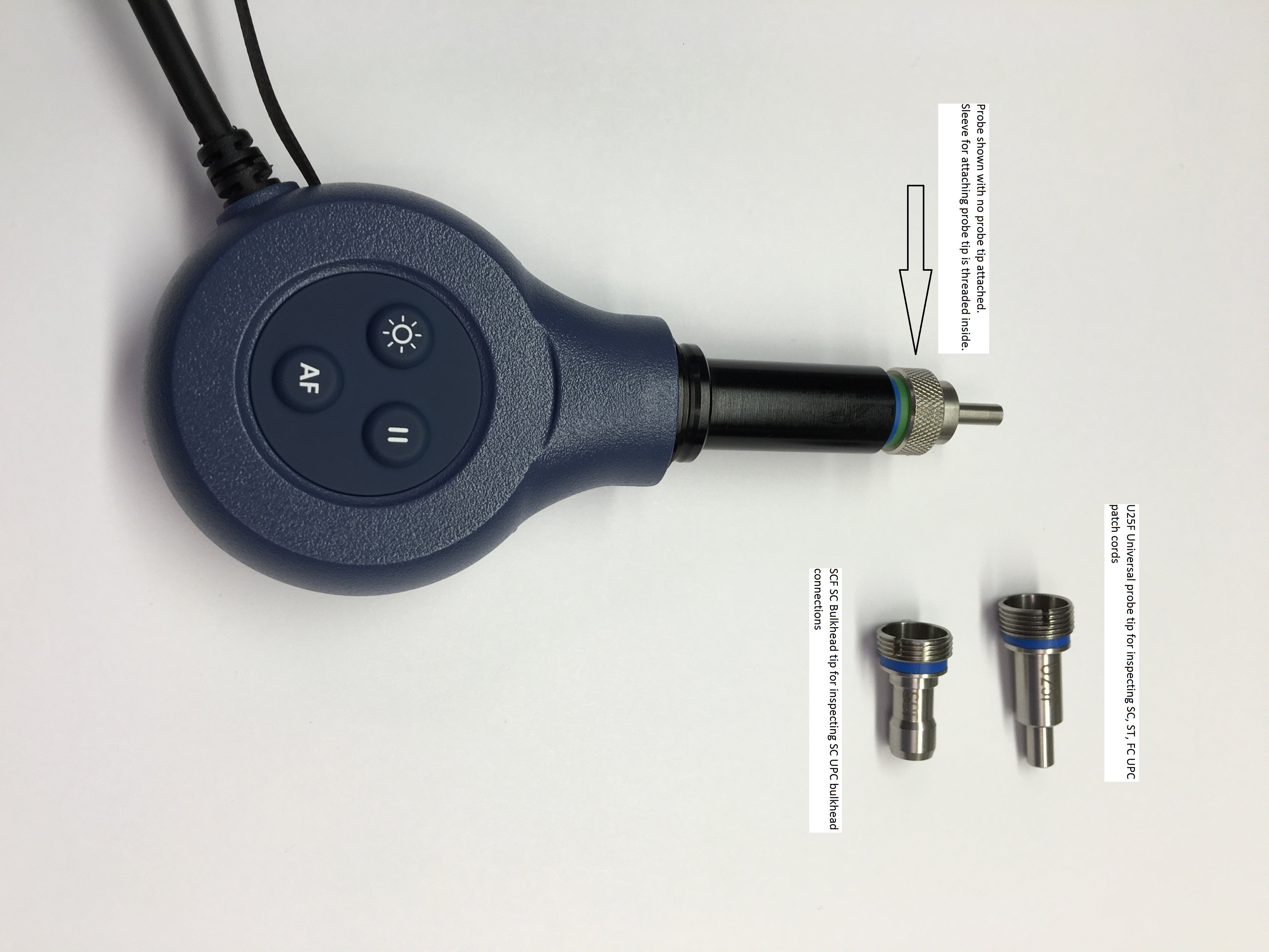
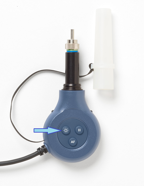
Probe with no tip attached:
Attach the appropriate probe tip for the connector type you wish to inspect.
After confirming you have installed the correct probe tip, insert the fiber connector ferrule into the probe tip and press (AF) AutoFocus.
Pressing the AF button on the probe also bings the display out of Standby (display has gone dark due to period of inactivity).
可选: Press pause (F1) and then press (F3) to magnify the image on the display. You may press pause on the probe or on the FI-500 display.
Probe Tips
FI-500 comes standard with probe tips for inspecting SC, ST, FC, and LC UPC type fiber endfaces for fiber patch cords, and LC and SC UPC type fiber bulkhead ports.
The FI-500-U25F "Universal" probe tip is used to view SC, ST, and FC UPC type fiber connector endfaces on fiber patch cords.
All probe tips are threaded at the base externally, and they connect to the camera probe via the metal sleeve.
The metal sleeve is threaded internally, and it is permanently connected near the end of the camera probe.
Focus problems? Make sure that the probe tip is connected correctly to the end of the probe.
- To Remove the probe tip, hold the tip stationary with one hand hand and unscrew the sleeve in clockwise direction.
- To Install the probe tip, hold the tip stationary with one hand, engage the threads of the probe tip and the sleeve, and turn the sleeve in counter clockwise direction until you feel resistance. Finger tight is adequate, no tools are required. Some theads on the probe tips may remain visible after the tip is connected to the probe.
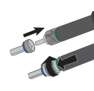 The example on the left shows installing the FI-500TP-LCF (LC Bulkhead) probe tip.
Fluke Networks offers Probe Tips for a variety of connector types for FT-500 available for purchase separately. The probe tips are specific to FI-500 and are not interchangeable with Fluke Networks FI-1000 or FT500 fiber scopes.
Port Bright
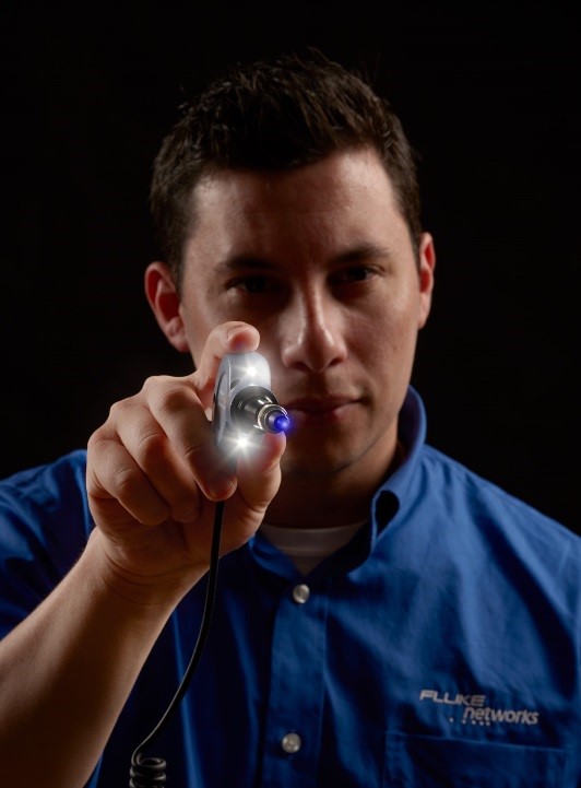
Press the Port Bright button on the camera probe and it illuminates the two white LEDs to help you see the bulkhead connection in low light conditions.
You can adjust the duration in Settings from 5, 10, 20 or 30 seconds.
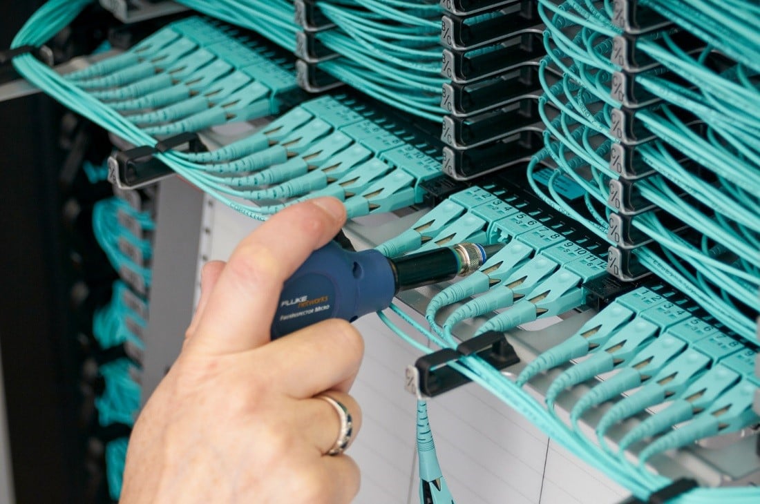
Bulkhead Port Inspection
Connect the appropriate bulkhead probe tip for the port you are inspecting and insert the probe tip into the bulkhead port.
Press the AF button on the FI-500 probe or on the display by pressing the F2 button.
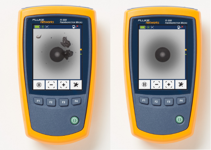
On the left is an example of a dirty fiber endface. If you see something like what is shown on the left (or worse), clean the fiber endface and inspect again.
The core should be clear of any debris as shown in the image on the right.
Do you need fiber cleaning supplies? Check out Fluke Networks Fiber Optic Cleaning Kits.


