Reducing the number of N/As appearing in the event table - DTX Compact OTDR
N/A will appear in the event table when the OTDR is unable to measure the loss at that event. An example is shown below in LinkWare Software. A receive fiber was used to ensure the far end connection (483.55 m) was measured. However, due to poor reflectance, the loss at this event was not measured. Note how the event at 483.55 m does not recover as quickly as it did at 0.00 m.
This can happen when the event you are trying to measure is within the attenuation deadzone (not the case here). If your connection is less than ideal, you will see additional reflectance. This will increase the observed attenuation deadzone, increasing the likelihood of the OTDR not being able to measure the loss at that event and reporting N/A in the event detail. All OTDRs rely on good reflectance to measure the loss of an event.
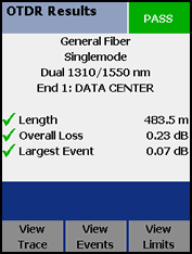
So a good reflectance value will reduce the chances of N/A appearing in the Event Table. But if the Test Limit does not have a reflectance limit, the technician running the OTDR will not be notified there is a reflectance issue. In the case of the result above, the technician would have been presented with the following screen at the end of the Autotest:
Before creating a custom test limit and specifying a reflectance value, you are going to have to decide on what value to use. There are three possible connector termination methods and the expected reflectance will change depending on which method you use.

This can happen when the event you are trying to measure is within the attenuation deadzone (not the case here). If your connection is less than ideal, you will see additional reflectance. This will increase the observed attenuation deadzone, increasing the likelihood of the OTDR not being able to measure the loss at that event and reporting N/A in the event detail. All OTDRs rely on good reflectance to measure the loss of an event.
So a good reflectance value will reduce the chances of N/A appearing in the Event Table. But if the Test Limit does not have a reflectance limit, the technician running the OTDR will not be notified there is a reflectance issue. In the case of the result above, the technician would have been presented with the following screen at the end of the Autotest:
Before creating a custom test limit and specifying a reflectance value, you are going to have to decide on what value to use. There are three possible connector termination methods and the expected reflectance will change depending on which method you use.
- Pigtails: These are pre-polished connectors with a length of fiber, hence the name. They are fusion spliced onto your installed fiber. They are made under strict controls in a factory and the vendor should be able to guarantee a minimum reflectance value. For singlemode UPC you can expect a value better than -40 dB, please talk to you vendor. For multimode UPC the minimum reflectance value specified by the vendor will probably be better than -35 dB. Again, it is critical to look at the data sheet for the pigtail you are using.
- Pre-polished/No epoxy: These are connectors that have been pre-polished in a factory under tight controls just as with pigtails. However, there is no length of fiber coming out of the connector. Instead, the fiber stops short in the middle of the connector. Within the connector is an index matching gel. The technician cleaves the installed fiber and inserts it into the connector. The fiber is then locked in place. Examples of this include SYSTIMAX Qwik Connectors™, Corning Unicam™, Belden Optimax® and Leviton Thread-Lock®. As with pigtails, check with the vendor to determine the reflectance specification. Please ensure you always use a precision cleaver during the installation.
- Field polished: This should be discouraged. It is very labor intensive and practically speaking, you will not achieve the level of reflectance found using a factory polished connector. With field polishing, you can expect your OTDR attenuation deadzones and reworking of connectors to increase. There may be an additional cost in the purchase of pre-polished connectors (mentioned above). However, this is easily recovered in the labor savings. Once you get familiar with these pre-polished connectors, your yields will increase and your labor cost will drop dramatically. Please contact your local distributor or representative about moving away from field polishing.
Setting a reflectance limit
In this example, the vendor supplying the pigtails has assured us that the minimum reflectance value is -40 dB @ 1310 nm and 1550 nm.
- Rotate the dial to SETUP.
- Highlight Fiber OTDR and press ENTER
- Highlight Test Limit and press ENTER.
- Press the F1 key (More).
- Highlight Custom and press ENTER.
- Press F1 (Create).
- 按 Enter。
- Press ENTER again to edit the Name (what you would like to call this test limit), press the SAVE when done.
- Make sure Use Default Values From is General Fiber, if not, change it now.
- Press F1 (Select Fiber).
- Highlight your fiber type and press ENTER.
- Highlight Event Reflectance and press ENTER.
- Enter your reflectance limit - in this example, -40 dB, press SAVE when done. (Make sure you enter a minus value!)
- Press SAVE again to store your new Custom Test Limit.
- Highlight your Custom Test Limit and press ENTER.
- Rotate the dial back to AUTOTEST - done.
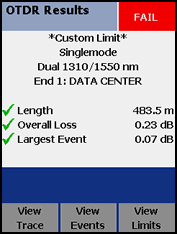
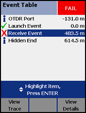
If we were to repeat the test on the link above with this new Custom Test Limit, the technician would see:
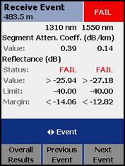
Since these are factory polished connectors, it should be a simple case of inspecting and cleaning the end faces of the installed connector and receive fiber. If this were a field polished connector, cleaning alone may not improve the reflectance. Mediocre field polishing can produce reflectance values as low as this.


