First action: Update your instrument to the latest firmware x.925.
Lets also check the instrument out as well.
Connect the two units together as shown in Figure 1 below.
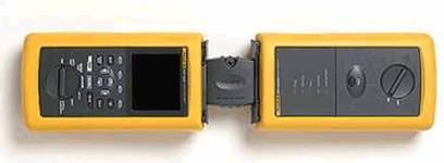
图 1. Self Calibration
-
Run the Self Test in SPECIAL FUNCTIONS
-
Set the analyzer to TIA Cat 6 Channel.
-
Run the AUTOTEST.
-
View the NEXT result.
-
You should see margins in excess of 20 dB.
-
If the margins are less than this, the unit may need to be returned a Fluke Service Center for Calibration. When returning the unit, be sure to put a note in the box saying that you are seeing noise warnings.
-
When this checks out to be fine, please read on.
Fluke DSP Series Cable Testers Noise Detection
The Fluke Networks DSP Series cable testers detect the presence of externally induced noise signals while performing the crosstalk (NEXT and FEXT) measurements. When the strength of this externally induced disturbance is judged to be significant, the tester provides a short warning message and changes measurement mode in order to accurately measure the actual NEXT and FEXT induced in the link. The final outcome provides an accurate measurement of the crosstalk generated internal to the cabling link-under-test (measured by the NEXT and/or FEXT parameters). Occasionally, the impact of the external noise is so severe that the tester cannot resolve the measurement.
The DSP Series testers judge the external noise to be significant when the magnitude of this disturbance endangers the accuracy of the test results. These testers filter out the externally induced noise component by increasing the number of samples taken during the measurement cycle. The user observes that the tester runs slower the test time has increased. The warning tells the operator that the slowing is not due to a malfunction of the tester but rather that this is due to the need to filter out the external noise components.
Avoid wasted time because of false failures.
When the measurement results are close to the test limits, external noise could be counted as crosstalk and could yield a false failure diagnostic. This false fail outcome could cause installers or network maintenance personnel a significant amount of wasted time. The installers would investigate cable termination and connections in the failing link, and they may possibly rework all of the termination and connections, only to find that the measurement outcome has not changed. They would eventually determine to replace the cabling link in question invest yet more time with once again the same outcome since the external noise source is most likely still present. It is therefore, important to accurately measure NEXT and FEXT without the contribution of any external noise sources. The Fluke Networks DSP Series testers accomplish this task.
What are the consequences for the network operation?
NEXT and FEXT are themselves noise signals. The Fluke Networks cable testers are very sensitive instruments with a noise floor above 110 dB in the lower regions of the frequency spectrum but not dropping below 85 dB for the higher frequencies. Installed cabling links very often pick up external noise that is above the noise floor of the cable tester and is detected by it. The DSP Series testers apply sophisticated algorithms to determine whether the measurement accuracy of NEXT and FEXT would be negatively influenced by the external noise.
The measurement accuracy requirements for high performance cabling such as Cat 5e and Cat 6 are affected by noise signals that may not impact the reliability of the digital signaling used by the network equipment. The fact that the tester issues a warning that external noise has been detected does not relate to network operation but instead to the need to complete the measurements compliant with the TIA Accuracy Level IIe or Level III.
Local area networks utilize digital signal encoding. Digital signal encoding is much more resilient to external noise than analog signaling. In conclusion, the warning message does not automatically imply that the network transmission is going to be affected by noise problems.
The sources of noise and how to identify them
If the tester displays the message that external noise has been detected, the user may want to determine the source of this noise and conclusively decide whether the detected noise disturbance will affect the network communications in a noticeable way. We must make a distinction between three forms of noise disturbances. (1) Impulse noise that is more commonly referred to as voltage or current spikes induced on the cabling (2) Random (white) noise distributed over the frequency spectrum (3) Alien crosstalk (crosstalk from wire-pairs in one cabling link to wire-pairs in an adjacent link)
1. Impulse Noise
If impulse noise is induced on the cabling link, the transmission will be affected every time a pulse or spike of significant magnitude and duration is generated on the cabling link. The DSP series testers provide a means to check the presence of impulse noise and the magnitude of the pulses. Connect the DSP series tester main and remote unit to the cabling link. Turn the rotary knob on the front panel of the main unit to the Monitor mode and select Impulse Noise. The tester will monitor the link and register voltage pulses that exceed a preset amplitude value. The tester reports the (1) number of spikes per second detected over the most recent one second interval (2) the average of the previous numbers over the period of monitoring, and (3) the maximum number of spikes that occurred in a one-second interval. The default threshold level for the detection and registration of impulse noise is 270 mV (determined by 10BASE-T specification in the IEEE 802.3i standard). This threshold level can be modified in 10 mV steps in the Setup menu of the testers. For high-speed network applications such as 1000BASE-T (Gigabit Ethernet), the recommended threshold value for impulse noise detection is 30 or 40 mV. If the tester at this threshold level detects very few (less than 1 in 100 seconds) pulses, the cabling will be able to deliver very good support for high speed applications such as Gigabit Ethernet (assuming the link passes the TIA/EIA Cat5e tests or the ISO 11801 Class D 2002 tests).
2. Random Noise
This noise disturbance may be generated by many sources ranging from wireless communications such as FM radio stations, police radio, building security, avionics for automated landing, and many more. A Spectrum Analyzer is needed to determine the frequency characteristics and the magnitude of the noise signals picked up by the cabling links. This laboratory type device can identify the frequencies of the signals (noise) on the link as well as the relative magnitude of the signals at the different frequencies. A small amount of noise (not detected by the Monitor mode) riding on top of the digital network signals does not materially affect the ability of the receivers in NIC cards and other active network devices to properly detect interpret the network signals.
3. 外部串音
Alien crosstalk is a special case of noise because it is induced by other cables in the same pathway. The detection is the same as those mentioned above.
Anytime a UTP link is tested in a cabling bundling in which some links are active the chances are very good that the tester will detect alien crosstalk especially when the traffic is 100BASE‑T and report the external noise detected message. Typically, this alien crosstalk will not impact the reliability of the network traffic. Primarily the Impulse test mode mentioned above should be used to determine whether the noise signal will affect the reliability of the network traffic.
Background Fluke Networks DSP Series Test Methodology
Since the Fluke Networks DSP Series testers utilize digital pulses as the stimulus for NEXT (FEXT) measurements, they also utilize a wide band input to make the NEXT (FEXT) measurements. The time-domain characteristic of the stimulus pulse combined with the wide band measurement input circuits allows the DSP Series testers to detect the presence of externally induced noise. This noise is asynchronous to the tester stimulus. The DSP Series testers always repeat each measurement (same stimulus pulse) several times and compute the average for the data samples obtained at each measurement sample point. This computed averages are compared against the individual sampled data values from which it was computed. The DSP Series testers determine the presence of external noise if corresponding data points obtained by consecutive measurements differ by more than a preset amount from their average value.
If the DSP Series tester determines that external noise is interfering with the NEXT or FEXT measurement, it displays the warning message and continues the measurement cycle by doubling the number of samples. It will continue to perform the same process and double the number of measurement samples a total of three times. These additional measurements are averaged to reduce or totally compensate for the component introduced by random (external) noise. Criteria have been developed to measure the rate of convergence which allows the DSP Series testers to optimize the number of measurements required to meet the stated accuracy of NEXT or FEXT excluding the disturbances introduced by the cabling environment.
In rare situation, the external noise may be so powerful that the DSP Series tester is unable to converge on what is to be considered the true NEXT/FEXT performance measure of a link. The DSP Series tester will abort the measurement cycle and display the appropriate warning message. In such cases, the user should perform the impulse monitor test or apply test equipment such as a Spectrum Analyzer to determine the frequency components and causes of the noise before taking any other corrective action.
结论
In summary, the digital test technology in the Fluke Networks DSP Series testers provide the unique capability to detect an external noise disturbance in the measurement of crosstalk generated within a cabling link. These testers use a sophisticated statistical measurement technique to assure that the NEXT/FEXT measurement mirrors the true performance of the link-under-test, excluding disturbances from the external environment.
The detected noise will not impede or interfere with the reliable operation of the network applications if both of the following condition are met
(a) the field tester completes the test and the test results yields a Pass
(b) The impulse noise test executed on the affected cabling links shows less that 0.01 average pulses per second when the detection threshold is set to 40 mV.
If a link is tested in a bundle with active links, a third condition may be added to ensure that alien crosstalk will not interfere with the network operations: the link passes with a NEXT headroom of 3 dB or better over the required performance specification of the network application.
If, on the other hand, the tester is unable to filter out the noise components induced by the environment and aborts the tests and/or a significant number of pulses are counted in the impulse noise test, the operation of the network may be affected. A further investigation into the causes of the external noise is highly recommended in order to arrive at a remedy or solution. Tools such a Spectrum Analyzer may be deployed to determine the frequencies at which noise signals are present and the relative magnitude of noise signals over the frequency range.
As a sanity check, connect the instruments together as if to perform a Self Calibration. Run the Autotest, if you see Noise Detected during this Autotest and you are not adjacent to sources of noise, and then the unit needs to be returned to a Fluke Networks Authorized Service Center.
|


