应用注释
如何使用 CertiFiber® Pro 测试安装的 Corning 多模 Pretium EDGE® Tap 模块
下载 PDF
概述
Corning Pretium EDGE® Tap 模块允许为了监控而被动接入光纤网络。模块中包含的分流器可将每个光纤信号分为两个输出,一个用于网络链路通信,一个用于监控。为确保已安装的模块运行正常并且满足 Corning 保修范围的要求,必须用已安装的模块来测量网络链路的损失。还可以选择从模块中测量接入链路的损失,以确保监控设备的链路运行正常。
有关通过 EDGE Tap 模块测量损失,请注意以下要点:
- 由于接入模块中的分流器在一个方向损失低,而在另一个方向损失高,因此只在一个方向测量通过模块的损失(不是双向测试)。
- 多模接入模块中的分流器针对 850 nm VCSEL(垂直腔面发射激光器)进行了优化,因此只用 850 nm 进行测试。
- 通过接入模块上的 LIVE 端口到远端 EDGE 模块的网络链路是双工的,因此要用 CertiFiber Pro 在“Smart Remote”(智能远程)模式下对其进行测试。通过 TAP 端口的链路均为输出,因此要用 CertiFiber Pro 在“Far End Source”(远端源)模式下对其进行测试。
本页内容
所需设备
- Versiv 主要及远程装置
- 两个 CertiFiber Pro 多模或四光损失测试套件 (OLTS) 模块
- 两条 LC/LC 50 μm 多模测试参考线
- 两条用于 50 μm/ 125 μm 光纤、SC/LC 连接器的环形通量测试参考线 (EF-TRC)
- 一个双工 LC/LC 适配器或两个简单 LC/LC 适配器
- 一条具有 Corning 通用极性的 MTP/LC 12 光纤扇出电缆
- 配有 LC 适配器的光纤检查显微镜(如 FiberInspector 视频探头)
- 用于 LC 和 MTP 连接器的光纤清洁用品
计算损失预算
CertiFiber Pro 测试仪中的自定义限制功能可为包含拼接和一类 MTP/MPO 模块的链路计算基于长度的损失预算。由于 EDGE Tap 模块和 EDGE 模块的损失不同,因此对于同时包含这两种模块类型的链路,必须手动计算损失预算。对于要在 EDGE 系统中测试的三条路径,必须为每条路径计算损失预算。然后,制定一个自定义测试限制,即将固定损失预算设置为损失预算值。
为每条链路中的三个路径计算损失预算,如图 1 所示:
- 网络链路。请注意,如果网络链路的长度不同,则需计算每条链路的预算。
- 近端的接入端口链路(可选)。
- 远端的接入端口链路(可选)。请注意,如果网络链路的长度不同,则需计算每条链路的预算。
表 1. 用于损失预算计算的值
| 组件 | 最大损失 (dB)* |
|---|---|
| OM4 EDGE 干线光纤 | 2.8 dB/km (0.00085 dB/ft) |
| MTP® 配对损失 | 0.35 |
| LC 配对损失 | 0.15 |
| EDGE Tap 模块中的 50/50 分流器 | 3.8 |
| EDGE Tap 模块中的 30/70 分流器 | 6.6/1.8 |
|
*在与具有相似性能规格的其他系统组件配对时的插入损失。 |
|
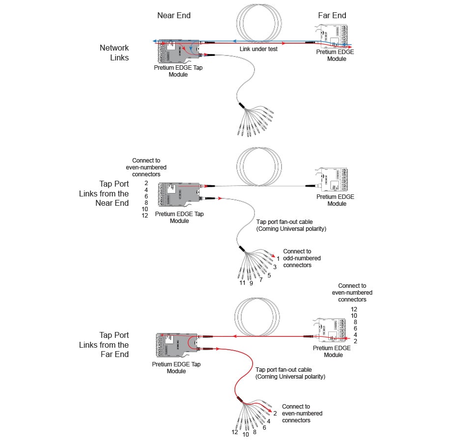
图 1. 用于损失预算计算的三条路径
图 2 显示从远端通过接入端口和扇出电缆进行测试的损失预算计算。请注意,此示例中不包括扇出电缆端的 LC 连接的损失。
计算包括 600 m 干线光纤和 10 m 接入端口扇出电缆的损失:
-
用于网络链路的 600 m OM4 EDGE 干线光纤的损失:
2.8 dB/km x .6 km = 1.68 dB -
用于接入端口线束的 10 m OM4 EDGE 干线光纤的损失:
2.8 dB/km x .01 km = 0.028 dB
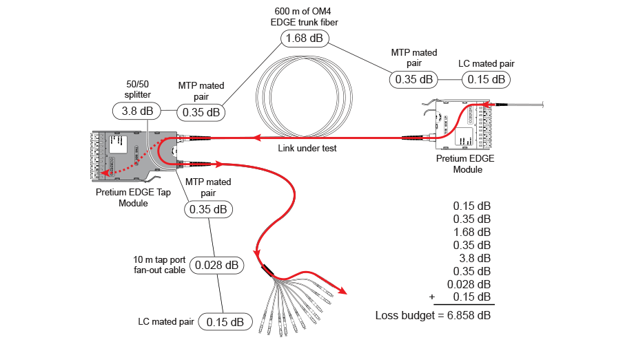
图 2. 用于测试网络链路的损失预算计算示例
有关损失预算计算的更多示例,请参阅 Corning 网站上的 Corning 标准推荐程序 (SRP) 文档号 003-126。
设置自定义测试限制
接下来,设置自定义测试限制,它将包括损失预算值,并且只在 850 nm 执行测试。您输入的第一个损失预算值将用于将要测试的第一个网络链路。
1. 在主屏幕上,轻触测试设置面板。
2. On the CHANGE TEST screen, tap a CertiFiber Pro test, then tap EDIT.
3. On the TEST SETUP screen, tap Test Limit, tap MORE, tap Custom, the tap MANAGE.
4. On the MANAGE CUSTOM screen, tap the Create panel.
5. On the NEW CUSTOM LIMIT screen, tap Enter New Limit Name, use the keyboard to enter a name, then tap DONE.
6. On the NEW CUSTOM LIMIT screen, enter these settings:
- Max lenth: Enter a value that is longer than the longest trunk in the fiber network.
- Loss Budget: Select Fixed.
- Wavelength specific settings: For Overall Loss @ 850 (dB), enter the calculated budget for the first network link you will test. 请注意,如果网络链路的长度不同,则需在测试每条链路之前相应更改此值。
- Leave the Overall Loss for all other wavelengths as N/A.
7. Tap SAVE.
8. One the TEST LIMIT screen, tap ![]() twice to go back to the TEST SETUP screen.
twice to go back to the TEST SETUP screen.
9. Tap TEST LIMIT, tap MORE, tap Custom, then tap the custom limit you made.
10. On the TEST SETUP screen, enter these settings:
- Test Type: Smart Remote
- Bi-Directional: Off
- Fiber Type: Select a fiber type that is correct for the type you will test.
- Reference Method: 1 Jumper. 这是您在设置参考时将在每个光纤路径中使用的跳线数。
- Connector Type: Select MPO Module. 测试仪保存此设置,以记录您所使用连接器的类型。此设置不会更改测试结果或测试仪显示的任何图表。
- No. of MPO Modules/Splices: The Total MPO Modules and Splices settings do not apply because you are using a fixed loss budget. Jumper Reference is 1.
11. On the TEST SETUP screen, tap SAVE.
测试网络链路
网络链路是双工连接,因此您使用“Smart Remote”(智能远程)模式来测试每条链路中的两条光纤。
为智能远程模式设置参考
- 打开测试仪,远程使其固定至少 5 分钟。如果测试仪温度高于或低于环境温度,则让其固定更长时间。
- 清洁并检查测试仪上的连接器,远程连接并测试参考线。
- On the home screen tap SET REF.
- On the SET REFERENCE screen, tap RUN WIZARD. Note: To only set the reference, and not measure the loss of your test reference cords, tap SKIP WIZARD on the SET REFERENCE screen.
- Make the connections to set the reference, as shown on the screen and in Figure 3, then tap NEXT to see the completed connections.
- To enter the length of the test reference cords you will add to connect to the link, tap TRC LENGTH on the SET REFERENCEscreen. 您输入的长度不会更改测试结果。测试仪会将该长度与结果一起保存,以符合 TIA 报告要求。
- Tap SET REFERENCE. If you did not use the connection wizard, go to “Test the Network Links in Smart Remote Mode” on page
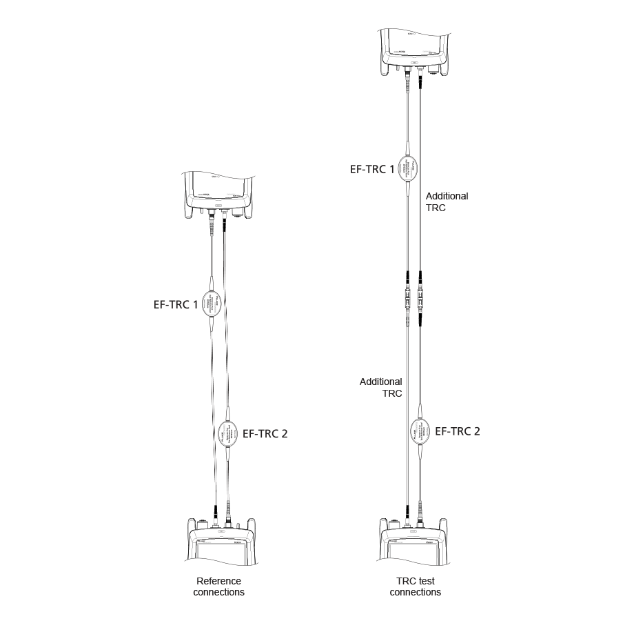
图 3. 用于智能远程模式的参考和 TRC 测试连接
如果您使用了连接向导,接下来请验证要添加的测试参考线 (TRC) 是否良好:
1. On the SET REFERENCE screen, when the reference procedure is completed, tap NEXT.
2. 从测试仪上的“INPUT”(输入)端口远程断开测试参考线,然后使用测试参考线和适配器进行连接,以验证 TRC,如屏幕和图 3 中所示。
3. Tap TRC VERIFICATION. 测试仪将测量并保存您所添加的测试参考线的损失。The IDs for these results start with “TRC”, show the date and time of the test, and have an ![]() for the test result. The tester shows a warning if the loss of a TRC is more than 0.15 dB. If the tester shows a warning, clean and inspect the connectors on the TRCs in the path that has too much loss, then set the reference and do the TRC verification again.
for the test result. The tester shows a warning if the loss of a TRC is more than 0.15 dB. If the tester shows a warning, clean and inspect the connectors on the TRCs in the path that has too much loss, then set the reference and do the TRC verification again.
在智能远程模式下测试网络链路
1.Clean and inspect the LC connectors on the EDGE Tap and EDGE modules.
2. 将 TRC 连接至链路的近端和远端,如图 4 所示。
3. 按下 B。
4. 如果测试通过,则保存结果。如果失败,则再次清洁并检查连接,或在必要时排除故障,然后再次测试。
5. If the network links are different lengths, change the value for the Overall Loss @ 850 (dB) in your custom limit to the applicable loss budget value for the next link. (TEST SETUP screen > Edit > Test Limit > MORE > Custom > MANAGE > Edit.)
6. 对所有链路重复步骤 2-5。
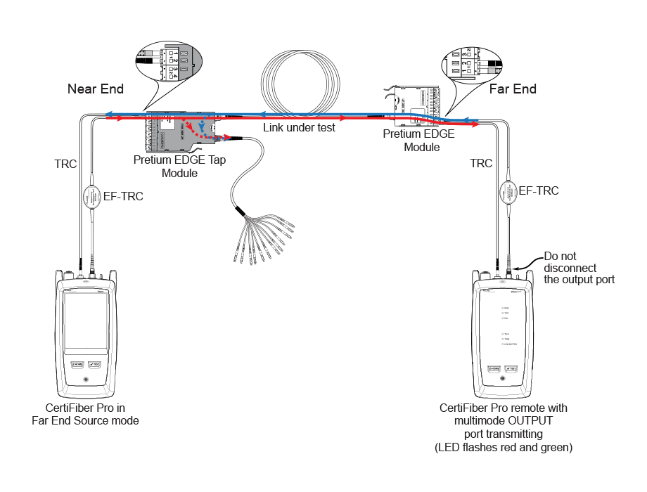
图 4. 用于测试网络链路的连接
测试 Tap 端口链路
无需为了符合 Corning 的保修范围要求而测试接入端口链路,但为了确保接入端口链路良好,可能需要执行此操作。
请注意,本文显示 TAP 端口已连接至 Corning 通用极性扇出电缆。还可以将 TAP 端口连接至其他 Pretium EDGE 模块。在此情况下,损失预算中将要增加其他 MTP 和 LC 配对损失,您会将 CertiFiber Pro 测试仪连接至模块中的 LC 端口。
TAP 端口连接
在将远程设备连接至近端的 EDGE Tap 模块时,要在接入端口扇出电缆上编号为奇数的连接器或连接至接入端口的 EDGE 模块上测量接入端口链路的损失。将远程设备连接至远端的 EDGE 模块时,要在接入端口扇出电缆上编号为偶数的连接器或连接至接入端口的 EDGE 模块上测量接入端口链路的损失。图 5 显示了这些连接。
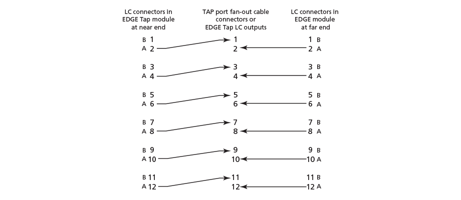
图 5. 从近端和远端模块到 TAP 端口电缆的连接
为远端源模式设置参考
由于所有接入端口连接都是输出,您将使用远端源模式来测试相同方向的所有接入端口链路,一次一个。设置参考并测试测试参考线 (TRC),如下所述:
1. 打开测试仪,远程使其固定至少 5 分钟。如果测试仪温度高于或低于环境温度,则让其固定更长时间。
2. 清洁并检查测试仪上的连接器,远程连接并测试参考线。
3. 在主屏幕上,轻触测试设置面板。
4. On the CHANGE TEST screen, tap the CertiFiber Pro test you set up before, then tap EDIT.
5. On the TEST SETUP screen tap Test Type, the tap Far End Source:
6. On the TEST SETUP screen, tap SAVE.
7. On the home screen tap SET REF.
8. In the TEST SETUP screen, tap SAVE.
9. On the SET PREFERENCE screen, tap RUN WIZARD. Note: to only SKIP WIZARDTo only set the reference, and not measure the loss of your test reference cords, tap the SET REFERENCE screen.
10. Make the connections to set the reference, as shown on the screen and in Figure 6, then tap NEXT to see the completed connections.
11. To enter the length of the test reference cords you will add to connect to the link, TRC LENGTH and the SET REFERENCEscreen. 您输入的长度不会更改测试结果。测试仪会将该长度与结果一起保存,以符合 TIA 报告要求。
12. 在 CertiFiber Pro 远程模块中,将 VFL 端口附近的按钮按下 3 秒,以打开多模源。
13. Tap SET REFERENCE.
14. 如果未使用连接向导,请转到第 13 页上的“Test the Tap Port Links from the Near End”(从近端测试 Tap 端口链路)。
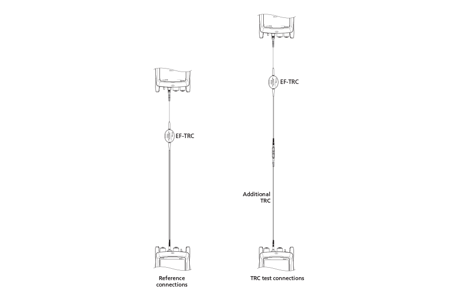
图 6. 用于远端源模式的参考和 TRC 测试连接
如果您使用了连接向导,下一步需要验证您要添加的测试参考线 (TRC) 是否良好:
1. On the SET PREFERENCE screen, when the reference procedure is completed, tap NEXT.
2. 从测试仪的“INPUT”(输入)端口测试参考线的连接,然后使用测试参考线和适配器建立连接,以验证 TRC,如屏幕和图 6 中所示。
3. Tap TRC VERIFICATON. 测试仪将测量并保存您所添加的测试参考线的损失。The ID for this results start with “TRC”, show the date and time of the test, and have an ![]() for the test result. The tester shows a warning if the loss of a TRC is more than 0.15 dB. If the tester shows a warning, clean and inspect the connectors on the TRC, then set the reference and do the TRC verification again.
for the test result. The tester shows a warning if the loss of a TRC is more than 0.15 dB. If the tester shows a warning, clean and inspect the connectors on the TRC, then set the reference and do the TRC verification again.
从近端测试 Tap 端口链路
1. Change the value for the Overall Loss @ 850 (dB) in your custom limit to the applicable loss budget value for the fiber path from the near end through the tap port. (TEST SETUP screen > Edit > Test Limit > MORE > Custom > MANAGE > Edit.)
2. 清洁并检查 EDGE Tap 模块(近端)上编号为偶数的 LC 连接器和接入端口扇出电缆或第三个 EDGE 模块上编号为奇数的连接器。
3. 如果要通过扇出电缆执行测试,则按图 7 所示建立连接;如果要通过第三个 EDGE 模块执行测试,则按图 8 所示建立连接。
4. If necessary, select End 1 or End 2. On the home screen, tap the Next ID: pnael, them tap the End 1/End 2 control to select an end.
5. Tap TEST on the main tester or press B on the main or remote tester.
6. 如果测试通过,则保存结果。如果失败,则再次清洁并检查连接,或在必要时排除故障,然后再次测试。
7. 对所有接入端口链路重复步骤 3-6。
注:To put End 1/End 2 results together in the same record, use LinkWare software to merge the results.
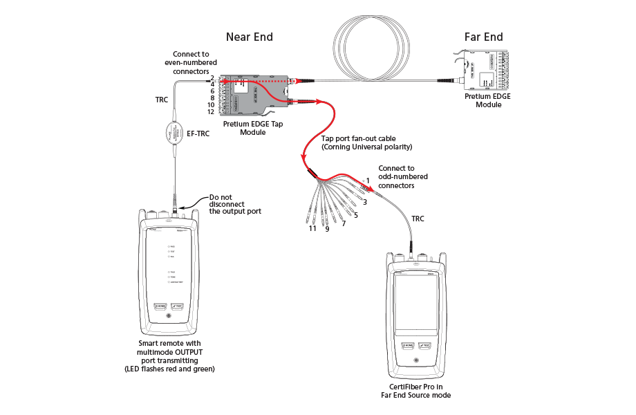
图 7. Connections for Testing the Tap Port Links
from the Near End through a Fan-Out Cable
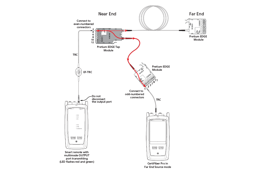
图 8. Connections for Testing the Tap Port Links
from the Near End through an EDGE Module
从远端测试 Tap 端口链路
1. Change the value for the Maximum Loss at 850 nm in your custom limit to the applicable loss budget value for the first tap port link you will test from the far end through the tap port.
2. 清洁并检查 EDGE 模块(远端)上编号为偶数的 LC 连接器以及接入端口扇出电缆或第三个 EDGE 模块上编号为偶数的连接器。
3. 如果要通过扇出电缆执行测试,则按图 9 所示建立连接;如果要通过第三个 EDGE 模块执行测试,则按图 10 所示建立连接。
4. If necessary, select End 1 or End 2. On the home screen, tap the Next ID: panel, then tap the End 1/End 2 control to select an end.
5. Tap TEST on the main tester or press B on the main or remote tester.
6. 如果测试通过,则保存结果。如果失败,则再次清洁并检查连接,或在必要时排除故障,然后再次测试。
7. If the network links are different lengths, change the value for the Maximum Loss at 850 nm in your custom limit to the applicable loss budget value for the next tap port link.
8. 对所有接入端口链路重复步骤 3-7。
Note:To put End 1/End 2 results together in the same record, use LinkWare software to merge the results.
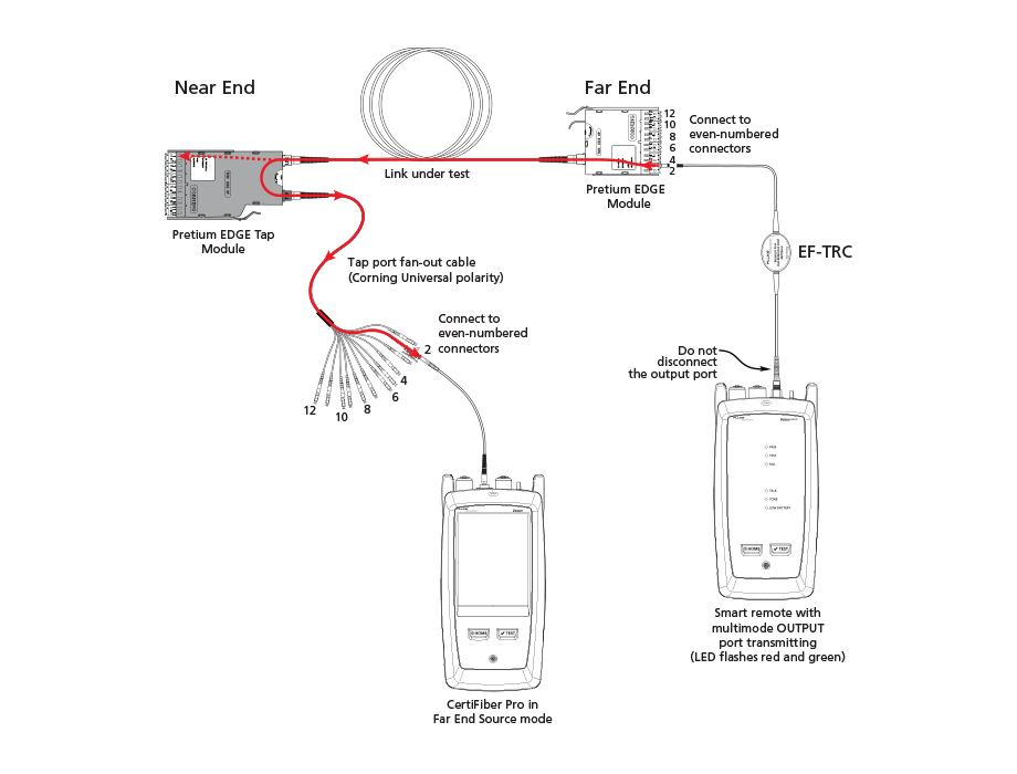
图 9. Connections for Testing the Tap Port Links
from the Far End through a Fan-Out Cable
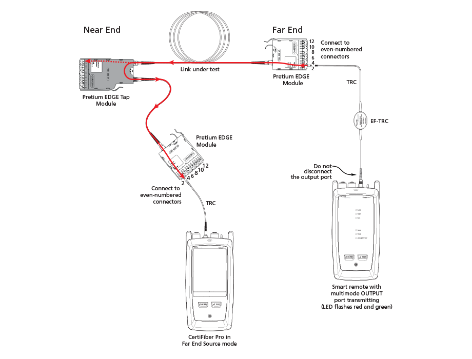
图 10. Connections for Testing the Tap Port Links
from the Far End through an EDGE Module


