Understanding insertion loss and loss budgets: Make or break an ICT career Digital Transformation and Industrial IoT age Part 3 of 3
June 19, 2019 / General, 101 learning, Installation and testing, Industrial Networks, Best Practices
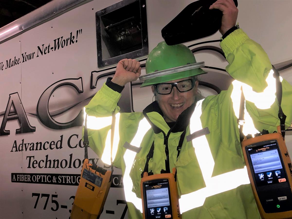
Expert Profile: Vangie Michenzi, Senior Fiber Optic Project Manager, Advanced Communication Technology Services
Part 3 of a three-part series
In this day and age, with everyone preparing for the future of 5G, the internet of things, and industrial automation, if you’re a contractor or technician you better know and understand loss budgets!
That’s the sage advice Vangie Michenzi shared in the last post of her Fluke Networks Expert Profile. Knowing all there is to know about insertion loss and loss budgets is what Vangie credits for making her one of the most in-demand troubleshooters in the West.
Understanding loss is the most important part of Vangie’s job and sets her apart from competitors - who often hire her and Advanced Communication Technology Services to find and fix all manner of fiber issues and problems.
In Vangie’s point of view, understanding “loss” and how loss budgets work hand-in-hand with transmission equipment is the skill and knowledge that will set a “great” ICT contractor and technician apart from “good” ones.
Understanding loss budgets will be THE most important part of an ICT technician’s job
Understanding loss means you can design networks properly, identify the good and bad in the network design, and then solve problems more easily.
“We are starting to see loss budgets get tighter and reflectance standards actually being enforced because speeds are going higher,” Vangie shared. “Understanding how loss and reflectance work and how to work with a loss budget helps you to look and identify the good and bad in the networks design.”
As Vangie points out, “It’s right there in the numbers, your OTDR will do a lot of the work for you. But it’s up to you to know loss and interpreting what, where and how far away the problems is.” For instance, it could be:
- Too many connection points causing a lot of the problems
- A bend or break in the fiber link
- A bad or broken connector or cheap pigtails
- Mixed fiber types in a single link
- There’s a UPC connected to an APC
- Dirt or contaminated connector somewhere along the line.
“You can diagnose many problems easily by recognizing the amount of loss associated with those particular problems,” Vangie says. “Plus, it helps to really know your OTDR and its capabilities. You can scale your range up and dial the pulse width way down to get a really good look at the fiber before you discover you’re in the wrong spot, losing time and money in the process.”
Vangie has a great troubleshooting example from a recent project where a contractor brought her in to help figure out a problem they couldn’t pinpoint. After donning the other contractor’s corporate logo shirt (they didn’t want to admit they had to call in an outside expert), Vangie went to work.
Remember, like all Western legends, the troubleshooter is only as good as the quality of their trusted tool, having the expertise to dial it in and shoot it, and to actually hit what they’re aiming at. Like Vangie stated above, she really knows how to use her OTDR: A Fluke Networks OptiFiber® Pro OTDR, of course.
In this case, Vangie connects her OTDR to what she knew to be a 12,000-foot length of fiber (knowledge). So, Vangie dials in her OTDR, takes the shot, it goes through its cycles, and tells her she was looking at a 3,000-foot piece of fiber. Of course, it was longer (knowledge), but based on her expertise and experience she knew it was likely heavy damage or some other kind of event occurring at 3,000 feet.
Turns out it was a piece of 50-micron OM4 spliced to a 50-micron OM2 (circa 1991). The original contractor told the customer they could use the old stuff but in reality, the old and the new stuff just don’t get along. Laser optimized 50 micron and step index fiber do not mix. Especially over long distances. But not everyone knows that (knowledge, again).
“It was immediately recognizable on my OTDR because the reflectance and loss were awful. But it depended on which way you shot it, right?” Vangie stated. “That is why I love the bidirectional averaging of the OptiFiber Pro.” The OptiFiber Pro OTDR’s SmartLoop™ bidirectional testingcapabilities, that is.
“I sent someone to the far end and they put my receive fiber between the two links and used the SmartLoop capability of my OTDR to look at it. It was immediately clear, you could see on a multimode link that we had gainers and a loss slope that rendered the link unusable,” explains Vangie.
Needless to say, everyone was happy at the end of the day, the contractor who brought Vangie in, the customer who wanted their network to work right, Vangie and her company, ACTS.
“As soon as I break out that yellow tester everybody feels more comfortable. Because all the electricians and all the engineers they're all very used to seeing Fluke Networks gear,” said Vangie. “It makes them feel like they’re in good hands.”
They most certainly are.
Resources


