OTDR launch packs – what’s bend-insensitive got to do with it?
September 28, 2016 / General, Installation and testing, Upgrading and troubleshooting, Industrial Networks
INTRODUCTION
Testing standards for measuring attenuation of installed multimode (and single-mode) cable plant require using launch and tail cords with OTDRs. Standards mandate that the optical fiber sub category (e.g. graded index 50 µm) be the same as the cabling under test. Proper use of OTDR launch cords is important because the last thing anyone wants to do is repeat a set of tests. Occasionally, certain fibers go “end of life” as new ones replace them but these changes need not be the concern of the customer. Users should depend on test suppliers to do the background work and testing to qualify new fiber. Such background work is common at Fluke Networks, goes mostly unnoticed, but removes the worry for users. This blog describes the typical testing that occurs in these situations. A full explanation of testing with an OTDR is not included in this blog.
Note When testing with a light source and power meter, the launch cord must use non-bend insensitive multimode fiber. See our blog post on that topic.
OTDR METHOD
Launch and tail cords (“launch packs”) are used with OTDRs when the attenuation of the “Cabling under Test”, connector “A”, and connector “B” must to be measured. See Figure 1 for this test set-up. Figure 1 is a simplified diagram and does not explain how bi-directional testing is done.
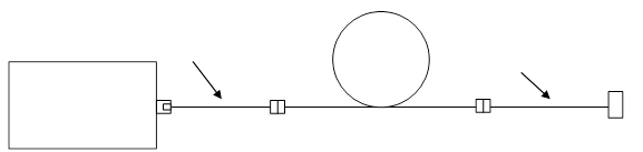
Figure 1 – Test measurement for OTDR method
For multimode testing, launch packs can be made with 50 µm or 62.5 µm optical fiber. Fluke Networks’ 62.5 µm OTDR launch packs have used the same fiber since they were first introduced because optical fiber suppliers made no change. However, for 50 µm optical fiber, bend insensitive multimode fiber (BIMMF) has become more popular (62.5 µm is not bend- insensitive). As a result, increased production of BIMMF has caused a decrease in production of “standard” 50 µm optical fiber. Since OTDR launch packs have traditionally used standard non-BIMMF, which has become “end of life”, testing was needed to consider using BIMMF in OTDR launch packs.
TESTING
A study by Fluke Networks was completed to determine if BIMMF could be used in OTDR launch and tail cords. The focus of the study was to compare OTDR measurements using launch packs with BIMMF and non-BIMMF fiber. Ideally, there would be no appreciable differences in measurements besides those attributed to differences in optical fiber geometry such as core diameter for example.
Optical fiber from 3 manufacturers was tested. Each data point shown in the following graphs represents an averaged bi-directional measurement. The final tally was averaged so that comparisons could be made easier. Testing was done using BIMMF launch packs on non-BIMMF cabling, with BIMMF launch packs on BIMMF cabling, and with non-BIMMF launch packs on non-BIMMF cabling (for baseline). Measurements were randomized as much as possible. Testing was done at 850 nm and 1300 nm but only results at 850 nm are shown herein. For the 5 graphs shown below, a total of 384 measurements were made.
In Figure 2, testing was done using non-BIMMF launch and tail cords on non-BIMMF cabling (baseline test). Randomly selected launch packs were used for the test. The average loss, over the 6 data points, using non-BIMMF test cords on non-BIMMF cabling was 0.76 dB. These samples were lab samples with lots of mileage on them and do not represent production quality so attenuation at connectors may be a higher than expected.
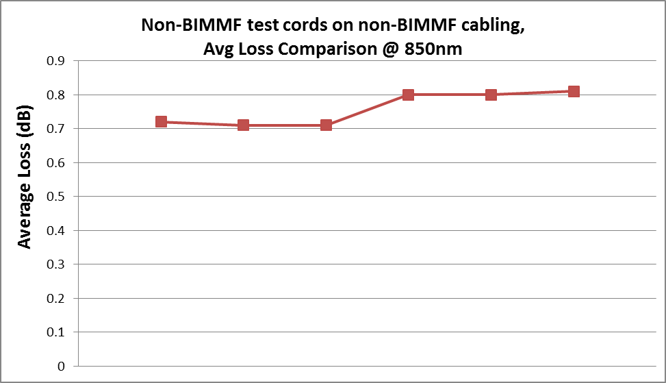
Figure 2 – Testing non-BIMMF cabling with non-BIMMF test cords
In Figure 3, testing was done using BIMMF test cords on non-BIMMF cabling. The averages for the three suppliers testing non-BIMMF cabling with BIMMF test cords were 0.55 dB (blue), 0.40 dB (green), and 0.37 dB (red).
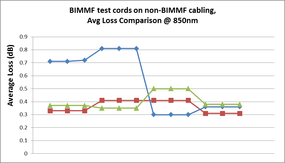
Figure 3 – Testing non-BIMMF cabling with BIMMF test cords
In Figure 4, testing was done using BIMMF test cords on BIMMF cabling. The averages for the three suppliers testing BIMMF cabling with BIMMF test cords were 0.41 dB (green), 0.35 dB (red), and 0.31 dB (blue). Note the colors are arbitrary and do not correspond to a specific fiber vendor.
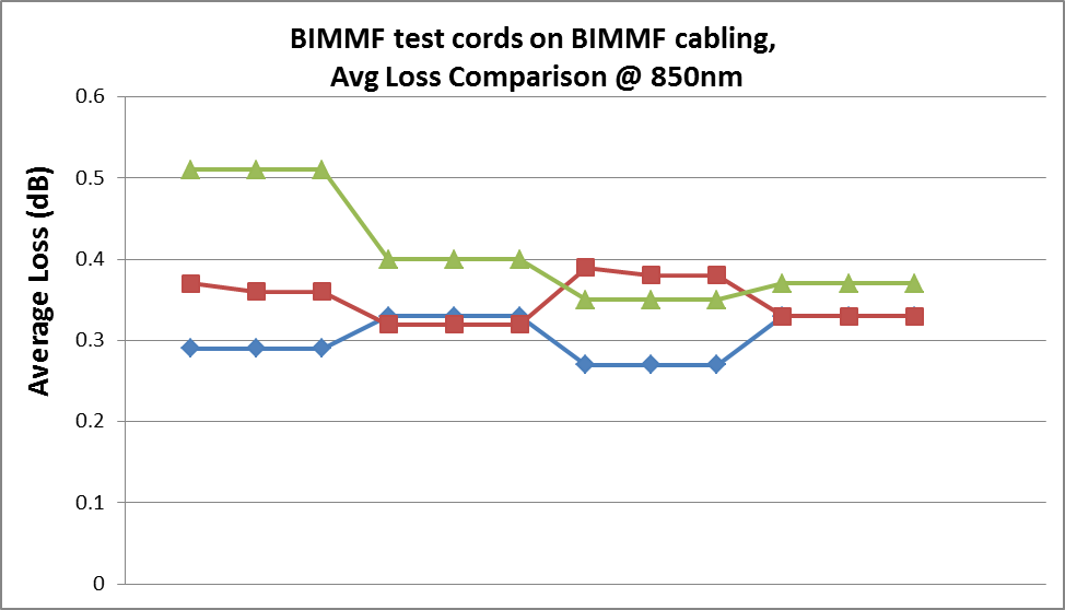
Figure 4 – Testing BIMMF cabling with BIMMF test cords
In Figure 5, testing was done using non-BIMMF test cords on BIMMF cabling. The averages for the three suppliers testing BIMMF cabling with non-BIMMF test cords were 0.73 dB (blue), 0.69 dB (red), and 0.57 dB (green). These are the same non-BIMMF launch packs used in Figure 1 with higher loss.
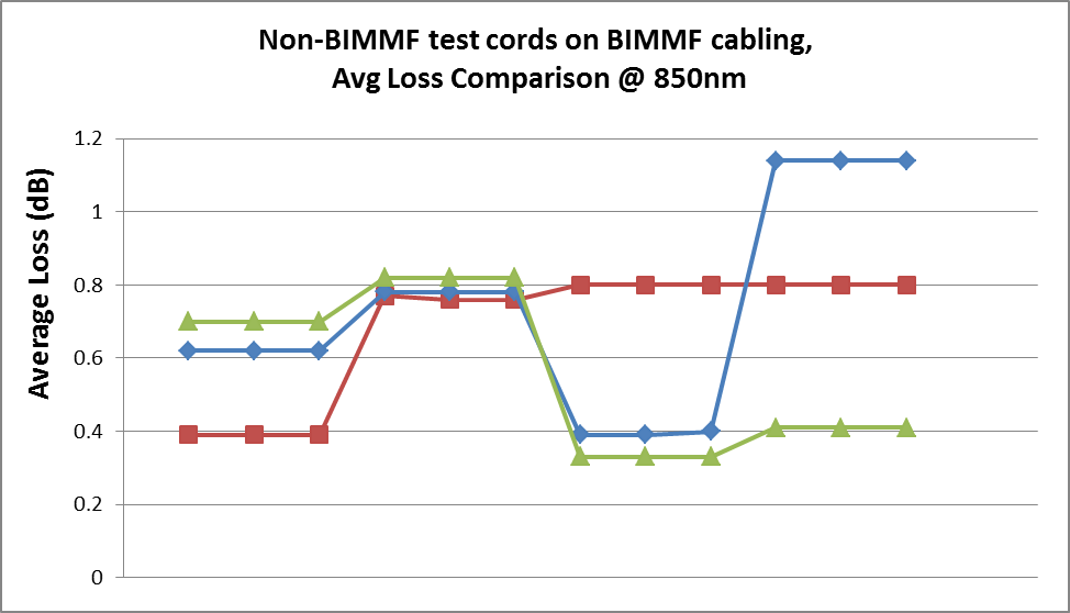
Figure 5 – Testing BIMMF cabling with non-BIMMF test cords
CONCLUSIONS.
BIMMF is the preferred fiber for new multimode installations while non-BIMMF is becoming more difficult to procure. Test equipment suppliers are left with making a decision on how to manage changing requirements. From the data presented, it is difficult to quantify a difference when testing installed multimode fiber cabling using an OTDR with either BIMMF or non-BIMMF test cords. Differences in core diameter, backscatter coefficients, and other fiber properties may influence attenuation measurements more than the fiber properties that improve bending performance. Since the data indicates little performance differences between BIMMF and non-BIMMF, the Fluke specification for the launch packs has been written to allow either. The take away from this blog is: Experts at Fluke Networks do the background work so you don’t have to worry about the test equipment.


最新报道 查看全部 >
什么是光纤?这里有一份指南
2024-03-20
网络和线缆测试终极指南
2024-03-13
选择绞合线缆还是实心线缆
2024-03-06
Fluke CableIQ™ 电缆鉴定测试仪与 LinkIQ™ 电缆 + 网络测试仪比较
2023-06-13
什么是回波损耗?
2023-02-14
布线认证比以往任何时候都更加重要的三个原因
2023-01-05
更多大众报道 查看全部 >
什么是光纤?这里有一份指南
2024-03-20
网络和线缆测试终极指南
2024-03-13
选择绞合线缆还是实心线缆
2024-03-06
如何延续 Versiv™ 投资的价值
2023-12-21
测试 MPTL 时正确方法是什么?
2023-08-22
承包商表示不值得冒逃避认证的风险
2023-07-06


©2006-2021 Fluke Corporation。保留所有权利。
RM2011, 20/F, SCITECH Tower, 22 Jianguomenwai Avenue, Chaoyang District, Beijing, China
地址:北京市朝阳区建国门外大街22号赛特大厦20层2011室
联系电话:400-8103435
沪ICP备11037028号-15![]()