Bi-Direction Testing with an OTDR
November 17, 2016 / General, 101 learning, Installation and testing, Upgrading and troubleshooting, Best Practices
STANDARD OR APPLICATION NOTE
Have you ever wondered how a Standard and an Application Note differ? No, the answer is not only that one is provided free by vendors. Both contain guidance and useful technical information so what is the difference? Well, a Standard is developed by many experts using consensus to provide accurate technical information and guidance while an Application Note, while technically accurate, is developed by one vendor to position their brand. One case in point is bi-directional testing using an OTDR. Many application notes have been written about bi-directional testing with an OTDR but what do the Standards say?
WHAT ARE WE TRYING TO MEASURE
First, let’s examine what is typically being measured. The attenuation measurement of an optical fiber link requires the measurement of the cabling under test as well as the two connections, “A” and “B”, on both ends of the link (see Figure 1). Notice that test cords are attached to both ends of the cabling under test. Otherwise, the attenuation (loss) at each connector could not be measured. The importance of measuring the end connectors is amplified when short fiber runs have fiber attenuation that is much lower than those of the connectors.
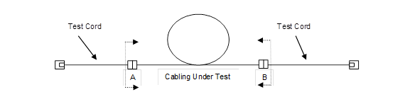
Figure 1 – Attenuation measurement of a link
WHAT IS A PROPER BI-DIRECTIONAL TEST
Launch and tail cords are used with OTDRs when the attenuation of the “Cabling under Test”, connector “A”, and connector “B” must to be measured (see Figure 2). A proper bi-directional test requires that only the OTDR be moved to the far end of the tail cord (see Figure 3). The launch cord and tail cord should never be removed from the cabling under test. Only the OTDR is moved. Doing otherwise would defeat the purpose of the test and waste time.
To reiterate, a bi-directional test consists of two measurements on the same optical fiber, made by launching light into opposite ends of that fiber, then averaging the attenuation at connectors without disconnecting the launch and tail cord from the cabling under test.
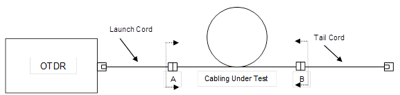
Figure 2 – Measurement for a bi-directional OTDR test, step 1

Figure 3 – Measurement for a bi-directional OTDR test, step 2
According to IEC 61280-4-1, multimode testing
In order to properly measure the first and last connection for bi-directional averaging, the launch and tail cords must remain in their initial measurement positions. Only the OTDR is moved. This will ensure that identical optical fibers are mated to the cabling under test so that the effects of mode field mismatch between the test cords and cabling can be averaged out.
If the launch and tail cord have identical backscattering characteristics and only the total attenuation of the link is required, it may be sufficient to carry out an OTDR test in one direction. However, it is rare that the launch and tail cord will have identical backscatter characteristics.
According to IEC 61280-4-2, single-mode testing
OTDR testing is carried out from both ends of the cabling when it contains splices or connectors (according to Figure 1, that is the case). Any differences in the component attenuation due to variations in backscattering coefficients can be cancelled out by averaging the component attenuation measurements taken from both ends of the system.
To accurately measure the first and last connection of the link using bi-directional averaging, the launch and tail cords remain in their initial measurement positions. This will ensure that identical optical fibers are mated to the cabling under test so that the effects of mode field mismatch between the test cords and cabling can be averaged out. An individual attenuation is defined as the half sum of the attenuation recorded from each end.

WHY DO IT
When an OTDR sends a pulse of light from its optical port into the fiber under test, reflected light is received on the same port. The reflected light can be Rayleigh backscattering which defines the fiber attenuation of an OTDR trace and/or Fresnel reflections which define, for example, connector return loss.
Rayleigh backscattering is fundamental to OTDR operation, and is the method OTDRs use to measure end to end loss, and discrete losses at splices and connectors. The backscatter coefficient is a measure of the amount of backscatter when an OTDR emits a 1 nano second pulse. It is defined by all fiber vendors for their fiber specification. To make accurate measurements, the OTDR backscatter coefficient (e.g. -79 dB) must be set in the OTDR.
Now for the bad news – backscatter coefficients vary along a fiber and from one supplier to the next. The effect - differences between test cords and cabling may cause variations in the attenuation or “gain” of individual connections. For example, when an optical fiber with a low backscatter coefficient is connected to a fiber with a higher backscatter coefficient, the OTDR will receive more optical power from the fiber with the higher backscatter coefficient. This can be interpreted as a reduction in the apparent attenuation and may even appear as a gain (negative attenuation). The effect is known as a gainer. Making an OTDR measurement from each end of the fiber then averaging the results cancels out the component attenuation variance.
WHAT DO THE STANDARDS SAY ABOUT THE TAIL CORD
In IEC 61280-4-2, attenuation measurements of installed single-mode optical fiber, provides guidance on the use of a tail cord. Considered a “non-recommended practice, measurement without a tail cord”, the Standard goes on to explain that with no tail cord, the attenuation of the connector at the end of the cabling is not taken into account. In other words, an improper test is performed wasting time and money. Further, if the cabling is short relative to the deadzone, a measurement is not possible. The only time testing without a tail cord is acceptable, according to the Standard, is for qualification of a repair of the cabling that has been tested before the damage.
SUMMARY
DO:
- Use a launch and tail cord when measuring the cabling under test
- Never disconnect the launch and tail cord from the cabling under test when testing in multiple directions
- Move only the OTDR by disconnecting from the launch cord and connecting to the tail cord
- Average the results from each measurement direction
- Pay attention to Standards
DON’T:
- Move the OTDR with the launch cord
- Neglect to use a tail cord
- Waste your time with an improper measurement
最新报道 查看全部 >
什么是光纤?这里有一份指南
2024-03-20
网络和线缆测试终极指南
2024-03-13
选择绞合线缆还是实心线缆
2024-03-06
Fluke CableIQ™ 电缆鉴定测试仪与 LinkIQ™ 电缆 + 网络测试仪比较
2023-06-13
什么是回波损耗?
2023-02-14
布线认证比以往任何时候都更加重要的三个原因
2023-01-05
更多大众报道 查看全部 >
什么是光纤?这里有一份指南
2024-03-20
网络和线缆测试终极指南
2024-03-13
选择绞合线缆还是实心线缆
2024-03-06
如何延续 Versiv™ 投资的价值
2023-12-21
测试 MPTL 时正确方法是什么?
2023-08-22
承包商表示不值得冒逃避认证的风险
2023-07-06


©2006-2021 Fluke Corporation。保留所有权利。
RM2011, 20/F, SCITECH Tower, 22 Jianguomenwai Avenue, Chaoyang District, Beijing, China
地址:北京市朝阳区建国门外大街22号赛特大厦20层2011室
联系电话:400-8103435
沪ICP备11037028号-15![]()