101 系列:以太网回到起点
2019 年 7 月 31 日 / General, 101 learning, Standard and Certification, Industrial Networks
It’s been more than 40 years since Bob Metcalfe published this simple diagram explaining his invention for interconnecting computers and printers at the Xerox Palo Alto Research Center in California. His patented multipoint data connection system with collision detection later became known as Ethernet.
Since the invention of Ethernet and the ability for computers to communicate and share information, our world has changed drastically. If you’re as old as I am, you’ve seen it all come to fruition – from email and the Internet, to the mobile phone and social media. With Ethernet as the de facto choice for transmitting data, many of us may take its functionality for granted without really understanding how it works.
Frame of Mind
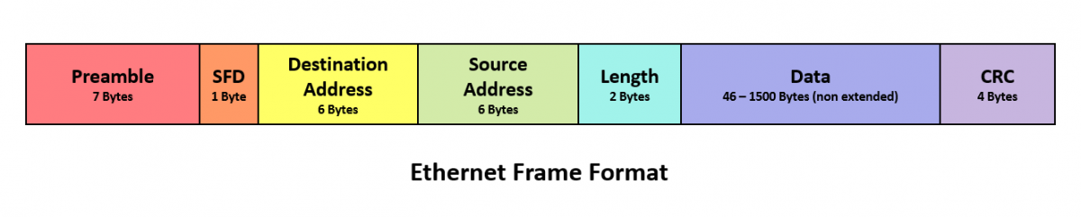
Ethernet sends information to and from devices in frames that commonly range in size from 64 to 1518 bytes. There are also extended (or jumbo) frames for sending greater amounts of data since processing data in one frame is more efficient than having it broken up into multiple smaller frames.
Ethernet frames include a Preamble that indicates that the frame is coming and allows the sender and receiver to establish a connection. Often considered part of the Preamble, the Start of Frame Delimiter (SFD) is a one-byte field that simply indicates the start of the frame.
Two of the most important parts of the Ethernet frame are the destination and the source addresses that contain the MAC address of the device for which the data is destined and the MAC address of the device that sent the data. MAC (Media Access Control) addresses are unique identification numbers integrated into the network interface cards of every device on the network.
The Length field of the frame simply tells the receiving device how large the frame is. The Data field holds the actual data being transmitted (also sometimes referred to as Payload). The last part of the frame is the CRC (Cyclic Redundancy Check) which includes the Frame Check Sequence used to discover any corrupted data.
From Here to There
To transmit frames from one device to another, Ethernet uses Carrier Sense, Multiple Access with Collision Detection (CSMA/CD).
In simple terms, Carrier Sense is the detection of the network and any signals being transmitted so a device knows when it’s clear to send. Multiple Access describes the fact that all devices on the network receive all the frames and check the destination address. Collision Detection is the ability for a device to recognize that it has attempted to transmit information at the same time as another device, cease transmitting and retransmit again when it’s clear to send. These retransmits use a random pause and retry to prevent devices from continuing to collide.
While Metcalfe’s first Ethernet drawing with just a few devices was quite feasible, as the number of devices trying to transmit on a single network segment increased, collisions increased, networks became congested and transmission slowed down. To reduce congestion, network segments need to be split into multiple segments that share information with each other. This is where switches come in.
Ethernet switches pick up every Ethernet transmission and forward it over the appropriate segment (i.e., link) to the destination address. This is what allows multiple devices on a network to communicate simultaneously. With Ethernet switching also came the ability to send and receive data at the same time using full-duplex Ethernet. Since devices in a modern switched network only communicate with the switch and not each other, there is no longer the need for most devices to detect collision.
Frames, Packets and Layers
When referring to Ethernet transmission, the terms frame and packet are often used interchangeably. However, they are not one and the same. Frames are used to transmit information between two nodes on the same network using MAC address, and they are generated at Layer 2 of the OSI model. In contrast, Packets are generated at Layer 3 and are used for transmitting information between different networks.
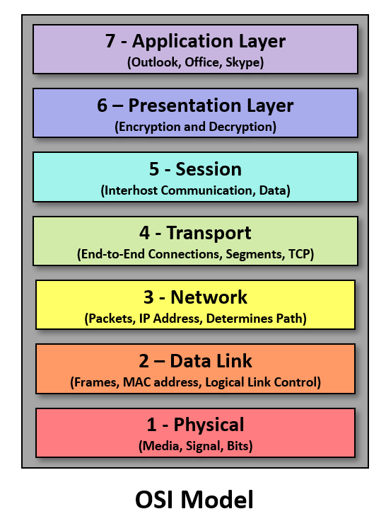
If you’re not familiar with the Open Systems Interconnection (OSI) model, it is the7-layer framework that describes how a network functions. Starting at the top, Layer 7 is the Application layer, which is essentially what the user encounters (think MS Office). Layer 6 is the Presentation layer where data is prepared for the network format (think encryption). Layer 5 is the Session layer where two nodes are set up to communicate with each other. Layer 4 is the Transport layer that coordinates the transmission of data and determines the data rate and ensure error-free transmission. Layer 3 is the Network layer where packets are routed to various networks. Layer 2 is the Data Link layer where information is sent from one device to another using MAC addresses and switching. And last but not least is Layer 1, the Physical layer that includes the physical media needed for transmission (i.e., cable and radio frequency), and all its requirements, including pin layouts, voltages, performance parameters and more.
In case you are wondering, Internet Protocol (IP) uses packets that are transmitted at Layer 3. Ethernet frames are encapsulated within IP packets by including additional information in the data field that includes IP addresses. Once that packet reaches its network switch, Layer 2 takes over and transmits frames based on the individual MAC address of the device. Think of it this way – An IP Address identifies a device on the Internet, which is why it is transmitted as a packet at Layer 3. If multiple devices reside on the same network, a portion of their IP address will be the same. IP addresses can also change when a device is moved to a different network. MAC addresses identify the actual individual network card of a device and are transmitted as frames at Layer 2. Multiple devices that reside on the same network will not have MAC addresses that resemble each other in any way. MAC addresses are set by the manufacturer and never change.
Need a product for testing Ethernet cables? MicroScanner PoE combines Ethernet, Power over Ethernet, and cable testing in one for faster installation and troubleshooting. Check it out here.
最新报道 查看全部 >
什么是光纤?这里有一份指南
2024-03-20
网络和线缆测试终极指南
2024-03-13
选择绞合线缆还是实心线缆
2024-03-06
Fluke CableIQ™ 电缆鉴定测试仪与 LinkIQ™ 电缆 + 网络测试仪比较
2023-06-13
什么是回波损耗?
2023-02-14
布线认证比以往任何时候都更加重要的三个原因
2023-01-05
更多大众报道 查看全部 >
什么是光纤?这里有一份指南
2024-03-20
网络和线缆测试终极指南
2024-03-13
选择绞合线缆还是实心线缆
2024-03-06
如何延续 Versiv™ 投资的价值
2023-12-21
测试 MPTL 时正确方法是什么?
2023-08-22
承包商表示不值得冒逃避认证的风险
2023-07-06


©2006-2021 Fluke Corporation。保留所有权利。
RM2011, 20/F, SCITECH Tower, 22 Jianguomenwai Avenue, Chaoyang District, Beijing, China
地址:北京市朝阳区建国门外大街22号赛特大厦20层2011室
联系电话:400-8103435
沪ICP备11037028号-15![]()