Troubleshooting Fusion Splices
December 13, 2017 / General, 101 learning, Installation and testing, Best Practices
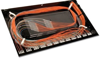
A fusion splice is when two fibers are fused together using an electric arc. Often used with pigtails for connecting 250-micron outside plant fiber to 900-micron inside plant fiber at the building entrance, fusion splicing is achieved with a fusion splicing machine after the fiber is properly cleaved with a precision cleaver. Fusion splicing can be done for a single fiber or for 12-fiber ribbon cable via mass fusion splicing that splices all 12 fibers at once.
Fusion splicing provides the lowest loss and least reflectance, and is considered the strongest and most reliable method of joining two fibers. When properly executed, a splice can exhibit a loss of less than 0.1dB. Let’s take a closer look at some considerations with locating and troubleshooting these high performing connection points.
I Can’t Locate My Splice!
With such a low loss and without the reflection you get with connectors, quality splices simply might not show up when using your OptiFiber™ Pro OTDR. But what if for some reason you actually want to locate a fusion splice, even a good quality one?
With a few simple adjustments to your settings using the Manual OTDR option, it’s quite easy. First, you may need to set your Loss Threshold on the OptiFiber Pro to locate events that have a loss less than 0.1dB. The OptiFiber Pro Auto setting for Loss Threshold is 0.15dB, which means it will only find events at or above this level. However, the Loss Threshold can be user defined from 0.01 to 1.50dB.
Note that smaller threshold values mean that the tester takes more measurements or uses wider pulse widths, which may increase test times or dead zones on the trace. A Loss Threshold of less than 0.15dB may also cause the OTDR to find false events due to inherent imperfections in the fiber.
Changing the Averaging Time can also help locate fusion splices. Averaging Time sets the number of measurements averaged together to create the final trace – longer times reduce noise to reveal more details like non-reflective splice events.
Identifying the Problem
With a good quality cleave and a fusion splice machine, it’s easy to achieve a proper splice. However, if the splices and slack are placed into the splice tray without properly following the tray’s cable guides, it could result in exceeding the bend radius of the fiber.
To locate this type of stress, you may need to test at two wavelengths – 850 and 1300nm for multimode and 1310 and 1550 for singlemode. At the higher wavelength, a stressed fiber will show significantly higher loss while normally the higher wavelength would show a lower loss. You may also need a VFL to determine if the problem is a cracked or kinked fiber rather than the pigtail connector as the event on the trace will typically show up at about the distance to the connector.
It’s also important to do bidirectional testing. If there is a backscatter mismatch between the pigtail fiber and the fiber it is being spliced to, it will look like a gainer (i.e., negative loss) in one direction and too much loss (i.e., false loss) in the other direction. If the test is done from both directions and the loss is averaged, the result is the actual loss.
To make bidirectional testing easy, the OptiFiber® Pro features a built-in “SmartLoop OTDR" Assistant that uses a loop at the remote end of a duplex fiber link, allowing you to test in both directions from one end. It also features on-board averaging of the two measurements to provide an accurate final loss measurement.
最新报道 查看全部 >
什么是光纤?这里有一份指南
2024-03-20
网络和线缆测试终极指南
2024-03-13
选择绞合线缆还是实心线缆
2024-03-06
Fluke CableIQ™ 电缆鉴定测试仪与 LinkIQ™ 电缆 + 网络测试仪比较
2023-06-13
什么是回波损耗?
2023-02-14
布线认证比以往任何时候都更加重要的三个原因
2023-01-05
更多大众报道 查看全部 >
什么是光纤?这里有一份指南
2024-03-20
网络和线缆测试终极指南
2024-03-13
选择绞合线缆还是实心线缆
2024-03-06
如何延续 Versiv™ 投资的价值
2023-12-21
测试 MPTL 时正确方法是什么?
2023-08-22
承包商表示不值得冒逃避认证的风险
2023-07-06


©2006-2021 Fluke Corporation。保留所有权利。
RM2011, 20/F, SCITECH Tower, 22 Jianguomenwai Avenue, Chaoyang District, Beijing, China
地址:北京市朝阳区建国门外大街22号赛特大厦20层2011室
联系电话:400-8103435
沪ICP备11037028号-15![]()