How to Measure the Loss in the APC Connector?
August 11, 2016 / General, 101 learning, Installation and testing, Upgrading and troubleshooting, Best Practices
This question often gets asked in my classes at the same time as when talking about launch methods using launch and tail fibers. So let’s talk about launch fiber compensation.
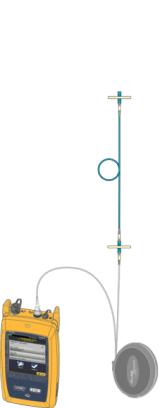
Launch fiber compensation: When we make an OTDR (Optical Time Domain Reflectometry) measurement, we use the launch cable to allow the trace to settle down after the pulse(s) are sent into the fiber, allowing us to see and analyse the start of the fiber being tested. This is because a large event will be seen in front of the connection on the trace usually caused by reflectance from the connector on the OTDR, thus not allowing us to make a good measurement of the first connection. The launch fiber also overcomes the issue of any dead zone (unseen event) that may occur if the pulse width is wider than the distance to a connector a short distance away from the OTDR connector.
An additional a short fiber cord may be added in between the OTDR and the launch fiber, usually called a “sacrificial cord” as it will sacrifice its connector rather than connector on the launch fiber.
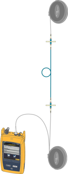
A launch fiber is typically used in-conjunction with a tail fiber. This allows the end of the measured fiber link to be measured. If a tail fiber is not used we are not able measure or analyse the end connector.
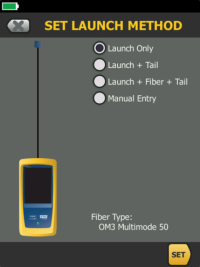
Launch methods: On Fluke Networks OptiFiber Pro there are four different methods that can be made using launch and tail fibers.
Launch only compensation: Where the length and loss of the launch fiber is removed from the results. However, this will result in the far end not being able to be analysed. To overcome this, the fiber should also be measured from the other end. If you use this compensation method you will not be able to do bi-directional averaging.
Launch and tail compensation: Where the length and loss of the launch and tail fibers are removed from the measurement. This method allows the far end connector as well as the near end connector of the fiber link to be evaluated. Another advantage of this method is it allows a fiber link to be evaluated even if the launch and tail fibers are different from the link under test or there are a number of different fibers within the link under test. This method is required to be used if bi-directional averaging is required.
Launch, fiber and tail compensation: Where the length and loss of the launch and tail fibers are removed from the measurement. This method has the advantage of allowing you to do the compensation with a connected link included. However, the disadvantage is you cannot access your launch fibers.
Manual compensation: This method of compensation removes the length and loss of the launch and tail fibers, but the cord lengths of both the launch and tail fibers are required to be entered manually on the OptiFiber Pro. This guarantees that the OptiFiber Pro knows where the first and last connectors are located in the link even if they have no measurable loss or reflectance.
This brings us back to the original question. When we make an OTDR measurement on a link that has an APC (Angled Physical Contact connector or sometimes called Angle Polish Connector) at the end of a link, it’s possible that the OTDR will not see the end of the link because the APC has no measurable reflectance or loss. To overcome this, the manual compensation method should be deployed on the OptiFiber Pro.
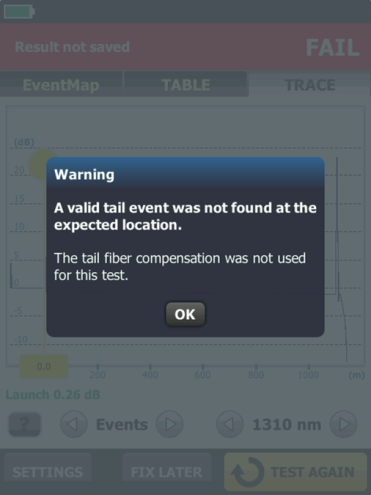
If we simply use the launch and tail compensation method, not manual compensation as mentioned, we may not have any measurable reflectance or loss at the end of the link. In this situation, the OptiFiber Pro produces the warning screen on the right.
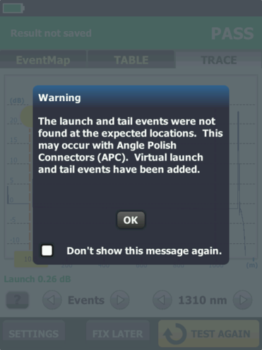
If we use the suggested manual compensation method, the OptiFiber Pro knows where the first and last connectors are in the link because we programmed in the length of the launch and tail fibers. When an OTDR measurement is made and no reflectance or loss is measured at the start or the end of the link, a virtual event will be marked on the trace. In addition this screen will be produced.
I hope this short article has helped you understand how an OTDR can test a link with an APC connector in the link and understand the different methods of launch compensation.
 Barry Lindsley has 44 years of experience in the Test and Measurement industry working with Tektronix, Fluke and Fluke Networks. Of which 23 years have been in the networks business. During this time he was working in either technical or combined technical and marketing roles. He also chaired the TIA (UK) Sig 11 group chairman working on CAT5E testing. For the last 3 years Barry has owned a consulting company which provides networking technical and marketing professional services.
最新报道 查看全部 >
什么是光纤?这里有一份指南
2024-03-20
网络和线缆测试终极指南
2024-03-13
选择绞合线缆还是实心线缆
2024-03-06
Fluke CableIQ™ 电缆鉴定测试仪与 LinkIQ™ 电缆 + 网络测试仪比较
2023-06-13
什么是回波损耗?
2023-02-14
布线认证比以往任何时候都更加重要的三个原因
2023-01-05
更多大众报道 查看全部 >
什么是光纤?这里有一份指南
2024-03-20
网络和线缆测试终极指南
2024-03-13
选择绞合线缆还是实心线缆
2024-03-06
如何延续 Versiv™ 投资的价值
2023-12-21
测试 MPTL 时正确方法是什么?
2023-08-22
承包商表示不值得冒逃避认证的风险
2023-07-06


©2006-2021 Fluke Corporation。保留所有权利。
RM2011, 20/F, SCITECH Tower, 22 Jianguomenwai Avenue, Chaoyang District, Beijing, China
地址:北京市朝阳区建国门外大街22号赛特大厦20层2011室
联系电话:400-8103435
沪ICP备11037028号-15![]()